Contributed by:
Bojanna Shantheyanda, Dr. Sreya Dutta, Kevin Coscia and David Schiemer Dynalene, Inc.
This article was published in Electronics Cooling Magazine, , Number 4, Volume 21. Click here to view
1.0 Background
Electronics has made its way into practically every aspect of modern life in the recent times. The introduction of the integrated circuit (IC), where several components such as diodes, transistors, resistors, and capacitors are placed on a single chip, revolutionized the electronic industry. The number of components packed in a single chip has increased steadily to Giga-Scale Integration (GSI) today with over a billion components per chip [1]. With a decrease in the size of the electronic components, there has been a dramatic increase in the amount of heat generated per unit volume, jeopardizing the safety and reliability of the electronic equipment. The failure rate of electronic components is doubled for every 10°C increase in the operating temperature. Therefore, thermal control has become increasingly important in the design and operation of the electronic equipment [2].
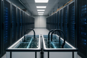
Air cooling has been the preferred cooling techniques for the electronics packages for decades. Combinations of natural, forced and mixed convection air cooling methods are still popular in most of the application due to its simple design, low costs, easy maintenance and high reliability [3]. However, air cooling is less effective compared to liquid cooling due to low thermal conductivity and its inefficiency towards heat removal by convection. Additionally, low density and low specific heat of air compared to liquids diminishes its thermal capacitance and hence, lessen its ability to store thermal energy without incurring unacceptable temperature rise [4].
A combination of fan and dedicated heat sink combinations for CPU cooling are expected to accommodate a heat flux of about 50 W/cm2 [5].
1.1 Liquid cooling
Liquid cooling is used in the applications involving power densities that are too high for safe dissipation by air cooling. With higher thermal conductivity compared to gases, liquids have much higher heat transfer coefficient [1]. Using high velocities and high pressures, liquid cooling can be used to remove heat up to 200 kW/cm2 [5]. Liquid cooling can be classified into different cooling techniques. Some of the techniques are:
1.2 Single and two phase liquid cooling
A single phase cooling loop usually consists of a pump, a heat exchanger (cold plate/mini or micro-channels), and a heat sink (radiator with a fan or a liquid to liquid heat exchanger with chilled water cooling) [6]. In a two phase cooling, phase change of the working coolant is used to absorbing the thermal energy from the electronic circuit [7]. Some of the two phase cooling applications are heat pipes, thermosyphons, vapor chambers, sub-cooled boiling, spray cooling, and direct immersion systems [7, 8, 9].
1.3 Active and passive liquid cooling
In passive cooling, external energy is not applied to remove the heat from the electronics. Examples of these systems are heat sink with fins, phase change systems, high conductivity chassis and heat pipes. In an active cooling system, external energy is used to remove the heat from the electronics. This system can help maintain the chip junction temperature independently to that of the ambient air temperature. Examples of these systems are pumped liquid cooling, pumped phase change systems and vapor compression system.
1.4 Indirect and direct liquid cooling
Liquid cooling, which can be achieved using indirect or direct means, is utilized in electronics applications having thermal power densities that may exceed safe dissipation through air cooling. Indirect liquid cooling is where heat dissipating electronic components is physically separated from the liquid, whereas in case of direct cooling, the components are in direct contact with the liquid coolant [4]. Most desired liquid coolants’ for the electronics cooling applications have good themophysical properties, high flash point and auto ignition temperature, compatible with materials of construction, good chemical and thermal stability, inexpensive, nontoxic and long shelf life. Good thermophysical properties for the liquid coolants are required in order to obtain both higher convective heat transfer coefficients and lower pumping power [10]. Deionized water is a good example of a widely used electronic coolant for indirect cooling applications. Other popular non-dielectric coolant chemistries used in indirect cooling applications are propylene glycol, ethylene glycol, ethanol/water, calcium chloride solution, potassium formate/acetate solution and liquid metals such as alloy of gallium, indium and tin (Ga-In-Sn) [10].
1.5 Electrical conductivity in an indirect, single phase active liquid cooling
The electrical conductivity of the liquid coolant becomes important in a direct cooling application because of the direct contact between the coolant and the electronics [11]. However, in indirect cooling applications the electrical conductivity can be important if there are leaks and/or spillage of the fluids onto the electronics. In the indirect cooling applications where water based fluids with corrosion inhibitors are generally used, the electrical conductivity of the liquid coolant mainly depends on the ion concentration in the fluid stream. Higher the ionic concentration, larger is the electrical conductivity of the fluid. The increase in the ion concentration in a closed loop fluid stream may occur due to ion leaching from metals and nonmetal components that the coolant fluid is in contact with. During operation, the electrical conductivity of the fluid may increase to a level which could be harmful for the cooling system.
Ion exchange resin can be used to remove the ionic substances that raise the electrical conductivity of the coolant in an electronics cooling application. They are bead like polymers that are capable of exchanging ions with ions in a solution that it get in contact.
In the present work, ion leaching tests were performed with various metals and polymers in both ultrapure deionized (DI) water, i.e. water which is treated to the highest levels of purity, and low electrical conductive ethylene glycol/water mixture, with the measured change in conductivity reported over time. Additionally, changes in the electrical conductivity of ultrapure DI water in an indirect, single phase, active cooling loop, with and without ion exchange resin are characterized with the findings reported. Finally, recommendation for design and estimation of the longevity of the ion exchange resin cartridge in an electronics cooling loop is discussed.
2.0 Experimentation
In this section, the experimental setup for measuring coolant electrical conductivity in both the ion leaching and closed loop indirect cooling experiments are described.
2.1 Long-term ion leaching experiment
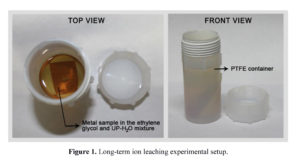
The experimental setup used for the long-term ion leaching analysis is shown in Figure 1. The experiment was performed using aluminum (AL3003), brass (B5665), stainless steel (304L), high-density polyethylene (HDPE), polypropylene, nylon, polyvinyl chloride (PVC), nitrile rubber (Buna-N), polyurethane and silicone samples immersed in:
- Ultra-pure distilled water (UP-H2O) with the electrical conductivity 0.5µS/cm, and
- Premade mixture of 50:50 ethylene glycol and UP-H2O, and nonionic inhibitors ( EG-LC).
The fluid and test sample were placed in a polytetrafluoroethylene (PTFE) container which were cleaned with distilled water, alcohol, UP-H2O and dried in ambient atmosphere. PTFE containers were chosen over borosilicate glass because they contain strong, compact bonds which are excellent at maintaining their original crystallinity, therefore, exhibiting lesser ion leaching capacity to the base fluid. The containers were charged with either UP-H2O or EG-LC. Metal and polymer coupons were rinsed with distilled water, alcohol, UP-H2O and polished to remove excess surface debris. The materials were placed in the containers and sealed with PTFE thread tape and PTFE lids. The samples were allowed to equilibrate at room temperature for two days before recording the initial electrical conductivity. In all tests fluid electrical conductivity was measured to an accuracy of ±1% using Oakton® CON 510/CON 6 Series meter which was calibrated prior to each measurement. A furnace was preheated to 80°C in ambient atmosphere and verified for heating uniformity to ±1°C at different locations, i.e. from the wall heating coils to the center of the furnace. The PTFE sample containers were then placed in the furnace when steady state temperatures were reached. The test setup was removed from the furnace every 168 hours (seven days), cooled to room temperature with the electrical conductivity of the fluid measured. The time for the samples to cool, measure, and place back in the oven was generally less than four hours. The electrical conductivity of the fluid sample was monitored for a total of 5000 hours (~208 days).
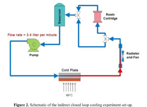
2.2 Closed loop, indirect cooling experimental set-up
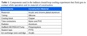
A schematic of the experimental setup is shown in Figure 2. Table 1 lists the components used for which the coolant made direct contact with. Before commencing each experiment, the test setup was rinsed with UP-H2O several times to remove any contaminants. The system was loaded with 230 ml of UP-H2O and was allowed to equilibrate at room temperature for an hour before recording the initial electrical conductivity, which was 1.72µS/cm. Fluid electrical conductivity was measured to an accuracy of ±1%. After the initial measurements, the copper cooling block was placed on a hot plate operated at 80 °C. During operation the fluid reservoir temperature was maintained at 34°C. The change in fluid electrical conductivity was monitored for 136 hours. The fluid from the system was collected and stored.
Similarly, closed loop test with ion exchange resin was carried out and the same cleaning procedures were employed. The initial electrical conductivity of the 230ml UP-H2O in the system measured 1.84µS/cm. An ion exchange resin cartridge (diameter = 38.1mm, height = 50.8 mm) containing 20g of Dowex mixed bed resin was installed in the fluid loop. Table 2 shows the test matrix that was used for both ion leaching and closed loop indirect cooling experiments.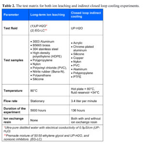 The change in electrical conductivity of the fluid samples when stirred with Dowex mixed bed ion exchange resin was tested. The fluid samples that were used for the testing are:
- Water from the closed loop, indirect cooling experiment that did not use resin cartridge and
- NaCl solution with the electrical conductivity of 11.82µS/cm.
0.1g of Dowex resin was added to 100g of fluid samples that was taken in a separate container. The mixture was stirred and change in the electrical conductivity at the room temperature was measured every hour.
2. Results and Discussion
2.1 Long-term ion leaching experiment
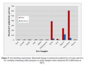
The measured change in the electrical conductivity of the UP-H2O and EG-LC test fluids containing polymer or metal when immersed for 5,000 hours at 80°C is shown Figure 3. To place in context the measurement results, the electrical conductivity of drinking water is typically less than 500µS/cm, river water between 50 to 1500µS/cm, industrial water less than 10,000µS/cm with seawater typically less than 50,000µS/cm [12].
The results indicate that metals contributed fewer ions into the fluids than plastics in both UP-H2O and EG-LC based coolants. This could be due to a thin metal oxide layer which may act as a barrier to ion leaching and cationic diffusion. Both UP-H2O and EG-LC fluid containing polypropylene and HDPE test samples exhibited the lowest electrical conductivity changes. Fluids containing polypropylene and HDPE exhibited the lowest electrical conductivity changes. This could be due to the short, rigid, linear chains which are less likely to contribute ions than longer branched chains with weaker intermolecular forces. Silicone also performed well in both test fluids, as polysiloxanes are generally chemically inert due to the high bond energy of the silicon-oxygen bond which would prevent degradation of the material into the fluid. It was observed that materials containing nitrogen groups, such as Buna-N rubber, polyurethane, and nylon had the largest electrical conductivity increases. It would be expected that PVC would produce similar results to those of PTFE and HDPE based on the rather similar chemical structures of the materials, however there may be other impurities present in the PVC, such as plasticizers, that may affect the electrical conductivity of the fluid. Additionally, chloride groups in PVC can also leach into the test fluid and can cause an increase in electrical conductivity.
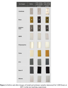
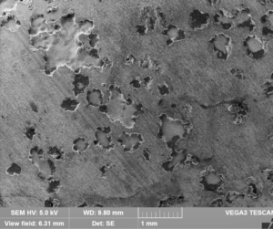
Figure 4 shows the before and after sample images of 5,000 hour testing of the metals and polymer samples, which was used in the ion leaching experiment. Buna-N rubber and polyurethane showed signs of degradation and thermal decomposition which suggests that their possible utility as a gasket or adhesive material at higher temperatures could lead to application issues. Polyurethane completely disintegrated into the test fluid by the end of 5000 hour test.
2.2 Closed loop, indirect cooling experiment
The measured change in electrical conductivity of the UP-H2O for 136 hours with and without ion exchange resin in the loop is shown in Figure 5. The electrical conductivity of the UP-H2O in a loop without resin cartridge increased by a factor of seven from 1.72µS/cm to 11.77µS/cm by the end of 136 hours of testing, an increase of approximately 1.77µS/cm per day. This indicates, during the course of the experiment, a constant ion leaching from the components when the fluid is in contact. The electrical conductivity of the UP-H2O in the loop containing the ion exchange resin cartridge consistently remained below 0.5µS/cm, indicating that the ion exchange resin was able to remove the ions that leached to the fluid stream, maintaining low electrical conductivity of the fluid during the duration of the experiment Figure 6 shows the change in the measured electrical conductivity of the fluid samples when stirred with the resin sample. The conductivity of the water sample from the closed loop experiment reduced by approximately 70% from 11.77µS/cm to 3.32µS/cm in six hours. Whereas, the electrical conductivity of the NaCl solution reduced by approximately 85% from 11.82µS/cm to 1.8µS/cm in six hours.
These results indicated that the capacity of the resin depends on the test fluid used for the experiment. This shows that different ions present in the fluid will result in different ion exchange capacity of the fluid. Therefore, calculating the ion exchange resin capacity with the fluid sample from the actual cooling loop is important. In order to calculate the accurate longevity of the resin cartridge that was used in the cooling loop experiment, the resin capacity with the water sample from the closed loop experiment was taken into consideration. Therefore, an ion exchange resin cartridge containing 20g of Dowex mixed bed resin may take on order 938 days to saturate. In other words, to maintain a low electrical conductivity, a resin cartridge with the dimension and weight specification as that of the resin cartridge used in the experiment, need to be changed every 30 months for the cooling system that was used in the experiment.
Conclusions
The long term ion leaching experiment showed that an increase in the electrical conductivity of the coolant fluid is contributed by ion leaching of both metals and polymers that is used in the closed loop cooling system. By determining the rate of increase in the electrical conductivity and the ion exchange capacity of the resin with the ions in the fluid used in the cooling system, the estimation of the longevity of the resin cartridge in an electronics cooling loop can be calculated.
References
- Yunus A. Cengel, “Cooling of electronics equipment” Heat and Mass Transfer: A Practical Approach, McGraw-Hill; 3rd edition, 2006, chapter 15, pp 1-69.
- Yunus A. Cengel, Adnan Menderes University, Afshin J. Ghajar, “Heat and Mass Transfer: Fundamentals and Applications” Oklahoma State University, 2015.
- Kakaç, Sadik “Introduction to ASI on Cooling of Electronics Systems” Cooling of Electronic Systems, NATO ASI Series, Volume 258, 1994, pp 1-15.
- Incropera, F., “Liquid Cooling of Electronic Devices by Single Phase Convection”, New York: John Wiley & Sons, 1999, pp. 1-14.
- Lasance, J.M Clemens, “Advances In High-Performance Cooling For Electronics”, Electronics Cooling, November 2005.
- Schmidt, R., “Liquid Cooling is Back,” Electronics Cooling, Vol. 11, No. 3, 2005, pp. 34-38.
- Johannes van Es and Henk Jan van Gerner, “Benefits and Drawbacks of Using Two-Phase Cooling Technologies in Military Platforms” Electronics Cooling, March, 2013.
- Lasance, C. and Simons, R., “Advances in High Performance Cooling for Electronics,” Electronics Cooling, Vol. 11, No. 4, 2005, pp. 22-39.
- Chrysler, G. M., Chu, R., and Simons, R.E., “Jet Impingement Boiling of a Dielectric Coolant in Narrow Gaps,” IEEE Transactions CHMT-Part A., Volume 18, No. 3, 1995, pp. 527-533.
- Mohapatra, Satish, “An Overview of Liquid Coolants for Electronics Cooling” Electronics Cooling, May 2006.
- Mohapatra, S. and Loikits, D., “Advances in Liquid Coolant Technologies for Electronics Cooling,” Proceedings of the 21st IEEE Semiconductor Thermal Measurement and Management Symposium, San Jose, CA, 2005, pp. 354-360.
- United States Environmental Protection Agency, “Water: Monitoring & Assessment,” http://water.epa.gov/type/watersheds/monitoring/2015, Last accessed November 15, 2015.


Trade Shows and Conferences